We’re ready to discuss an RV lithium battery installation that’s precise, methodical, and code-aware. We’ll outline chemistry choices, pack sizing, BMS strategy, wiring, enclosure, and safe integration with solar, shore power, and alternator charging. Our approach emphasizes verifiable documentation, proper fusing, and thermal management. We’ll present a clear workflow and checklists, then pointer you toward potential pitfalls and maintenance steps. If you want a dependable, scalable solution, there are critical details we’ll need to address next.
Key Takeaways
- Identify the right RV lithium chemistry (LiFePO4, NMC, or LiMn2O4) by voltage, BMS support, safety, and charging tolerance.
- Size the system by cataloging loads, duty cycles, surge, and climate to determine usable capacity and margin.
- Plan an integrated charging system (solar, alternator, shore power) with priority logic and unified control loops.
- Choose a safe BMS with proper protections, wiring, enclosure venting, and code-compliant installation practices.
- Provide a detailed installation workflow: fusing, wire sizing, BMS integration, monitoring setup, and routine safety labeling.
Identify the Right RV Lithium Chemistry
Which lithium chemistry fits our RV needs best? We assess cell format, energy density, cycle life, and thermal behavior to select a practical solution. We compare LiFePO4, NMC, and LiMn2O4 based on pack voltage, available BMS support, and charging profiles. Our focus is stable, repeatable performance under varying environmental conditions, not theoretical hype. We evaluate battery chemistry against our safety standards, including thermal runaway risk mitigation, cell balancing, and enclosure design. We require consistent state-of-charge behavior, manageable weight, and compatibility with existing alternator and solar inputs. We document the reasoning, verify manufacturers’ data sheets, and confirm manufacturer-specified safety standards. Our conclusion aligns with project constraints, ensuring reliable operations and clear, traceable compliance for the RV system.
Assess Power Needs and Choose System Size
We start by assessing your daily power needs and peak loads to establish a baseline for system sizing. Next, we translate those requirements into a battery capacity and inverter/charger specification that align with your usage patterns. Finally, we select a conservative margin to ensure reliable performance and longevity under varying conditions.
Assess Power Needs
Assessing power needs is the essential first step in sizing your RV lithium system. We begin by cataloging loads, defining duty cycles, and estimating surge requirements for each circuit. We quantify continuous versus intermittent draw, then translate it into amp-hours per day and peak power in watts. We account for seasonal variation, climate, and occupancy to avoid oversizing or undersizing. We document device efficiencies, startup currents, and inverter losses, using conservative margins to accommodate aging components. We emphasize careful sourcing for battery chemistry, BMS features, and charger compatibility to maintain system longevity. We also outline a cooling strategy, ensuring thermal management supports sustained performance under load. This disciplined assessment guides subsequent design decisions and prevents premature system stress.
System Size Selection
Is the next step to translate our power audit into a concrete system size that meets peak and runtime needs? We approach system sizing with a disciplined method that ties load profiles to battery chemistry and efficiency. We quantify reserve margins and derating factors to ensure reliability across operating temperatures. Our goal is a balanced, scalable pack that handles peak draw without unnecessary overbuild.
1) Define daily and peak loads from the audit and map to usable capacity.
2) Apply derating for temperature, aging, and inverter efficiency to determine effective energy.
3) Select a battery chemistry that optimizes cycle life, safety, and charging tolerance.
4) Verify runtime goals against contingency and expansion options, documenting all assumptions.
Plan an Integrated Charging System (Solar, Alternator, Shore Power)
We plan an integrated charging system that coordinates solar, alternator, and shore power to maximize efficiency and battery life. We’ll align solar-Alternator timing, manage shore power input, and implement a clear battery management strategy with monitoring and safeguards. This discussion introduces concrete controls, interfaces, and sequencing to guarantee safe, reliable charging under varying RV loads.
Solar-Alternator Coordination
To create a cohesive charging system, we’ll integrate solar, alternator, and shore power so their outputs coordinate automatically. We approach solar management and alternator integration as a single control loop, minimizing timing conflicts and maximizing efficiency. Our method aligns charge profiles, prevents cross-conduction, and protects battery health.
- Define charger setpoints that balance solar input with engine idle output.
- Implement priority logic to favor solar when available, then supplement with alternator power.
- Use a common DC-DC controller to unify voltage and current limits.
- Monitor state-of-charge, temperature, and system health to adapt charging stages in real time.
This coordinated scheme reduces idle drain, improves fill rates, and extends lithium longevity.
Shore Power Integration
Shore power integration acts as the backbone of an integrated charging system, coordinating with solar and alternator outputs to maintain stable, efficient battery conditions. We design a seamless interface that prioritizes lithium chemistry safety and reliability, enabling controlled charging profiles and automatic switching between sources. Our approach specifies input filtering, voltage and current monitoring, and smart sequencing to prevent overvoltage, undercurrent, and thermal excursion. We implement shore power detection with appropriate isolation, GFCI protection, and DC-DC conversion as needed for balanced pack charging. Charging limits are aligned to battery chemistry, temperature, and state of charge, with fail-safe handoff to alternate sources. Documentation covers connector standards, wiring diagrams, and diagnostic steps, ensuring technicians verify setpoints, interlocks, and regulator compliance.
Battery Management Strategy
A robust Battery Management Strategy coordinates solar, alternator, and shore power to preserve lithium pack health while delivering reliable charge management. We implement an integrated charging plan that prioritizes high-voltage bulk, controlled absorption, and safe float termination, minimizing solar efficiency losses and avoiding overcharging. Our approach relies on smart charging profiles, state-of-charge tracking, and temperature-aware limits to reduce battery aging while sustaining pack performance.
- Define charging priorities by source availability and battery state.
- Apply temperature-compensated limits to prevent aging and thermal stress.
- Use coordinated VMS/PMIC logic to sequence sources and prevent cross-conduction.
- Monitor SOC, voltage, current, and health indicators, adjusting as thresholds evolve.
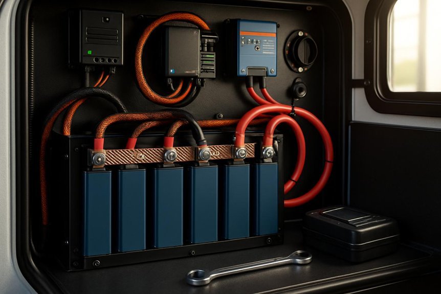
Pick a Safe, Code-Friendly BMS and Wiring Strategy
Selecting a safe, code-friendly BMS and wiring strategy starts with aligning the battery management system’s specs to our pack chemistry, voltage, and current demands, then confirming that wiring gauges, fusing, and enclosure clearances meet applicable codes. We evaluate BMS features like overcharge, overdischarge, balance, and temperature monitoring, selecting a model with redundant protections and proper communication interfaces. Our wiring plan prioritizes safe wiring, correct gauge sizing, proper insulation, and short, routed paths to minimize resistance and heat. We document fuse ratings, conductor insulation, and enclosure venting per local codes. This approach emphasizes battery safety and reliable protection, enabling predictable performance while simplifying maintenance.
| Parameter | Requirement |
|---|---|
| Voltage range | 12V–96V |
| Protection | Short‑circuit, thermal, overcurrent |
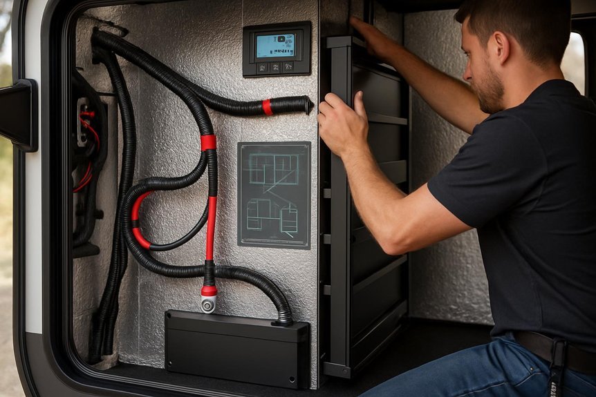
Mounting, Enclosure, and Venting for RV Use
Mounting, enclosure, and venting for RV use must align with our BMS and wiring plan to guarantee safe, code-compliant operation in mobile conditions. We approach mounting considerations with rigid attention to weight distribution, vibration resistance, and access for maintenance. Enclosure placement prioritizes airflow, moisture protection, and theft deterrence, while preserving compartment integrity. We also plan venting paths to prevent gas buildup and to allow for thermal equilibrium during usage.
- Confirm mounting points with load ratings and secure fasteners.
- Select enclosure locations that maximize cooling airflow and minimize heat transfer.
- Establish vent routes to outdoor air, avoiding interior condensation.
- Document clearances for service access and safety labeling.
Fusing, Wire Gauges, and Electrical Protection
When sizing and coordinating fuses, wire gauges, and overall electrical protection, we start from the system requirements and work toward practical implementation. We establish the acceptable voltage drop, current draw profiles, and peak surge behavior, then translate these into fuse ratings and conductor sizes. Fusing safety hinges on matching protection type (fast- or slow-blow) to load characteristics and insulation ratings. We select wire gauges that minimize heat, voltage loss, and resistance, while accommodating temperature derating and bundle spacing. Short-circuit protection is specified with clear tripCurrent targets and coordination intervals to prevent cascading failures. All connectors must be rated for continuous operation at system voltage. Documentation includes fuse and wire gauge selections, protective enclosures, and label visibility for maintenance.
Integrate the BMS and Set Up System Monitoring
How do we seamlessly integrate the BMS and establish robust system monitoring for a RV lithium setup? We approach integration with precise wiring, validated communication protocols, and standardized naming. We prioritize reliable data flow between the BMS, shunt, and inverter, while filtering irrelevant topic chatter to maintain focus on essential metrics. Monitoring screens should expose state of charge, cell balance, temperatures, and cable currents in real time, with alarm thresholds calibrated to safe limits. We avoid unnecessary instrumentation that adds noise or nonessential detail.
- Verify CAN/RS485 or I2C connections and address mapping
- Calibrate SOC, voltage, and temperature sensors per spec sheets
- Configure alarms and data logging intervals
- Validate end-to-end communication during initial burn-in
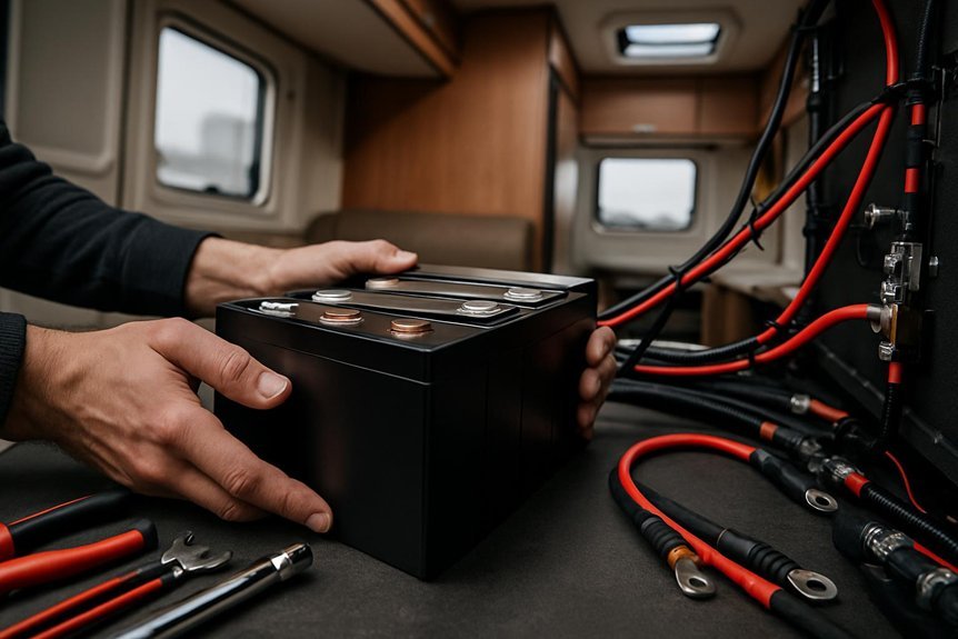
Step-by-Step Installation Workflow and Checklist
To implement the BMS integration and system monitoring we just outlined, we’ll now lay out a precise step-by-step installation workflow and a practical checklist. We begin with carefully selecting mounting location that aligns with weight distribution, accessibility, and ventilation. Securely fasten the battery pack using provided hardware, ensuring rails or brackets are level and vibration-isolated. Verify battery polarity and connector integrity before wiring; route cables away from heat sources and moving parts. Connect BMS data lines, shunt, and main power leads per manufacturer diagrams, then power up in diagnostics mode. Confirm voltage, current, and cell balance readings within spec. Document serials, fuse ratings, and airflow paths. Factor in thermal considerations, confirming adequate cooling or heating as required. Perform functional test, then finalize with an installation log and safety confirmation.
Common Pitfalls, Maintenance, and Troubleshooting
Common pitfalls tend to arise from overlook and misinterpretation of the system’s data. We address these issues directly, focusing on reliable maintenance, prompt troubleshooting, and clear data interpretation. We outline practical steps to verify sensible operation, monitor temperature, and confirm correct interconnects. By observing habitat considerations and maintaining balanced weight distribution, we minimize risk and improve efficiency.
- Inspect battery enclosure airflow and ambient temperature, ensuring venting and cooling are unobstructed.
- Verify BMS logs for voltage, current, and cell balance, and schedule regular diagnostic checks.
- Confirm connections, fuses, and cabling are clean, tight, and free from corrosion or damage.
- Reconcile load profiles with manufacturer guidance, updating settings after any system modification.
Frequently Asked Questions
How Long Do Lithium Batteries Last in RV Use?
We typically see 5–15 years for lithium batteries in RV use, depending on cycles and maintenance. We prioritize lithium safety, monitor cell balance, and consider battery warranties; with proper care, longevity improves and performance stays stable.
Can I Mix Lithium Brands in One System?
Yes, we don’t recommend mixing brands due to compatibility considerations and differing battery chemistries; ensure uniform chemistry and matched specs to avoid performance issues and safety risks in your system.
What Is the Ideal Lithium Cycle Life Under VA Ratings?
We envision a steady heartbeat of battery chemistry, aiming for a cycle life around 2,000–3,000 full cycles under typical VA-rated loads. We compare wear, monitor temps, and guard degradation to protect our system’s durability.
Do Lithium Packs Require Gas or Heat Venting?
Lithium packs generally require gas venting and heat management. We implement controlled vent paths and thermal monitoring, ensuring safe pressure relief and temperature limits while charging, discharging, or balancing, to prevent thermal runaway and maintain performance in RV applications.
How Often Should BMS Firmware Be Updated on RV Packs?
We update BMS firmware on RV packs annually, balancing risk and optimization with a cautious cadence. We prioritize lithium maintenance and lifecycle planning, yet avoid unnecessary updates, ensuring stable performance and clear, repeatable update cadence for all users.
Conclusion
We’ve laid out a precise, methodical road map for RV lithium installations, from chemistry choices to safe charging integration and monitoring. By aligning pack size, BMS strategy, and enclosure with code-friendly wiring and proper fusing, you’ll gain reliability and traceability. Stick to the workflow, verify ratings, and document every step for maintenance ease. If a snag appears, we’ll diagnose it together, channeling the calm focus of a navigator—yes, even in a sunlit, modern-day, steampunk world.

