We know safety and reliability matter, so we’ll start with careful chemistry choice, sizing, and derating to prevent premature failures. We’ll outline a practical path from battery chemistry and C-rate to BMS selection and wiring diagrams, then verify protection, grounding, and enclosure fit. Our approach is methodical, not theoretical, and we’ll flag common pitfalls early. If you want a robust install, this framework will guide every decisive step—but there’s more to confirm before you proceed.
Key Takeaways
- Choose appropriate lithium chemistry (NMC/NCA for energy, LFP for safety) based on duty cycle, temperature, and aging targets.
- Size capacity from load, autonomy, and depth-of-discharge to meet runtime and derate for aging.
- Define BMS, fuses, wiring, and safety features with precise protections and monitoring for safe integration.
- Plan thermal management and enclosure layout to maintain temps, airflow, and service access.
- Validate installation with checks for SOC alignment, voltage/current limits, wiring integrity, and protection test procedures.
Choose Lithium Chemistry and Capacity: C-Rate, Lifecycle, and Budget
Choosing the right lithium chemistry and capacity is essential for reliability and cost effectiveness. We approach chemistry selection by matching chemistry traits to our load profile, temperature range, and safety requirements. We compare NMC, LFP, and NCA in terms of energy density, cycle life, and thermal behavior, then identify the best fit for our duty cycle. Next, capacity sizing begins with load and desired autonomy, then accounts for depth of discharge targets and aging derating. We quantify C-rate compatibility, ensuring charge and discharge currents stay within specified limits to preserve longevity. Lifecycle impacts drive our budget, balancing upfront cost against long-term replacement frequency and efficiency losses. Finally, we document constraints, risks, and validation tests to confirm the chosen chemistry and capacity meet project goals.
Size Cooling, Design Ventilation, and Allocate Mounting Space
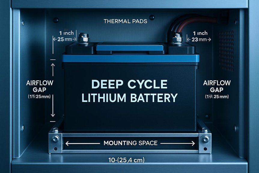
We will outline a clear allocation strategy for mounting space, ensuring we reserve adequate room for cooling and future upgrades. Our approach covers the cooling system layout, ventilation paths, and necessary clearance to prevent hot spots and ease maintenance. By aligning mounting geometry with component access and airflow requirements, we establish a precise, scalable baseline for safe operation.
Size Allocation Strategy
How should we size the allocation for cooling, ventilation, and mounting space? We approach this with a precise workflow: establish system thermal mass, rate of heat generation, and ambient conditions; then determine minimum clearances required for airflow, service access, and mounting stability. We allocate space to accommodate a conservative cooling margin, sufficient venting pathways, and rigid mounting points that minimize vibration transfer. We model enclosure volume against expected battery pack heat output, factoring derating during peak cycles. We incorporate planning safety as a design constraint, ensuring human access and maintenance paths remain unobstructed. We weigh budget tradeoffs by comparing passive versus active cooling, material rigidity, and mounting efficiency, selecting a configuration that maintains safe temperatures without overbuilding. Documentation captures dimensions, tolerances, and installation notes for reproducibility.
Cooling System Layout
What governs a reliable cooling system layout is a disciplined balance of thermal demand, airflow paths, and mounting rigidity, all aligned with the enclosure geometry. We define cooling needs from cell chemistry, current draw, and ambient conditions, then size cooling capacity accordingly. We map cooling airflow along return and supply channels to minimize turbulence and pressure drop, selecting ducting and baffles that preserve a uniform temperature profile. We allocate mounting space to secure modules with vibration dampening, allowing for service access without obstructing airflow. Enclosure sealing is integral; gasket integrity and minimal gaps reduce leaks that disrupt convection. We establish clear routing for cables and sensors to avoid thermal hotspots. Documentation covers schematics, clearances, and verification tests to confirm predictable performance.
Ventilation and Clearance
Sizing the cooling and allocating space begins with aligning ventilation design to the enclosure layout established earlier. We approach ventilation and clearance methodically, detailing requirements before installation. First, we identify ventilation requirements to prevent heat buildup, quantify airflow needs, and specify intake and exhaust paths. Next, we apply clearance guidelines around each battery module, balancing service access with thermal safety and wiring routing. We specify minimum distances to walls, vents, and equipment, and establish a uniform spacing pattern to avoid hot spots. We then allocate mounting space to accommodate fans, ducts, and cable harnesses, ensuring structural support and vibration isolation. Finally, we verify that the layout preserves on-site inspection access and aligns with safety standards for maintenance and monitoring.
Select a Safe, Compatible BMS for Your Pack
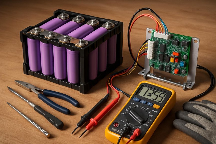
Choosing the right BMS is essential for safety and performance; we select one that matches your pack’s chemistry, cell count, and current requirements. We begin by confirming topology: series and parallel configuration, cell balance needs, and charge/discharge limits. Next, we verify voltage, current, and temperature sensing ranges align with your cells and charger. We favor BMS units that provide precise balancing, robust over/under voltage protection, and reliable insulation monitoring. We assess communication interfaces (CAN, I2C, or UART) for integration with our monitor system, ensuring compatibility with safety interlocks. We validate fault handling, arming thresholds, and reboot behavior under fault conditions. Throughout, safety awareness and installation best practices guide wiring, enclosure, and grounding, minimizing stray currents and thermal hotspots. Finally, document settings and perform a controlled, methodical verification.
Gather Fuses, Cables, and Protection Devices
With the BMS configured, we turn to gathering the components that guard and connect the pack: fuses, cables, and protection devices.
- fuse selection: choose fast-acting, automotive-grade types matched to pack current ratings
- wire gauge: select insulation-rated cable diameters to handle peak currents safely
- protection devices: install battery-side breakers and DC isolators per system requirements
- terminals and lugs: use corrosion-resistant hardware with proper torque
- routing and shielding: plan clean, short runs to minimize voltage drop and heat
We verify compatibility with the BMS and cells, confirm current ratings, and document part IDs. This step minimizes parasitic losses and ensures protection redundancy. Once sorted, wiring and testing proceed with confidence.
Draft a Practical Wiring Diagram for Your System
To draft a practical wiring diagram, we begin by outlining the system topology, then map each component to its electrical node to guarantee clear connections and minimal confusion during assembly. We systematically document conductor sizes, insulation, and expected loads, ensuring compatibility with our battery management strategy. We identify main power paths, critical interlocks, and serviceable branches, then annotate junctions with color codes and reference designators for rapid verification. Our diagram integrates battery management interfaces, shunt resistors, fuses, and protection devices, while respecting enclosure constraints and thermal considerations. We emphasize modular wiring harnesses that simplify assembly and future maintenance, detailing connector types, polarity, and routing. Finally, we include a revision block, version history, and notes for field checks, ensuring the diagram remains a precise, actionable reference during installation.
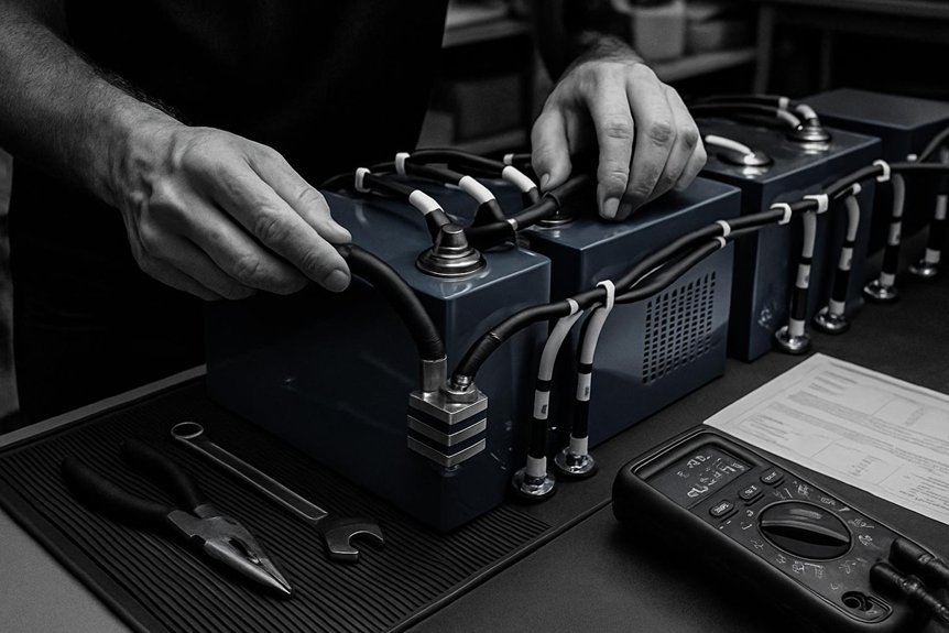
Install the Battery Safely: Placement, Isolation, and Grounding
The battery must be placed in a secure, accessible location that supports safe operation and easy maintenance, and we’ll start by selecting a position that minimizes heat exposure and vibration while allowing for proper enclosure ventilation.
- Assess ambient temperature and ensure consistent cooling paths to the battery enclosure
- Choose a dry, corrosion-resistant surface with vibration dampening where feasible
- Establish clear access for inspection, maintenance, and cable routing
- Implement isolation practices using predetermined disconnects and enclosures
- Verify grounding per system design, connecting to a dedicated earth or chassis ground
We’ll document placement safety decisions, confirm isolation practices are in place, and test fit before final wiring.
Commission and Safety Tests: Voltage, Current, and Protection Checks
We will begin with voltage checks to verify cell balance and total pack voltage, followed by current measurements to confirm proper charging and discharging behavior. Next, we will implement protection and monitoring steps to guarantee overvoltage, undervoltage, overcurrent, and thermal safeguards are active and logging is functional. This section sets the baseline for safe operation by documenting acceptable ranges and establishing immediate actions if deviations occur.
Voltage and Safety Checks
How do we verify a safe, functional setup before cycling a deep‑cycle lithium battery? We perform structured voltage, current, and protection checks to confirm readiness and compliance with setup criteria and safety protocols. Our approach is methodical, documenting readings, tolerances, and any deviations for action.
- Confirm initial state of charge aligns with system design
- Verify voltages across terminals match spec sheets within tolerance
- Measure charging and discharging current limits to ensure protection thresholds
- Check polarity, wiring continuity, and connector integrity
- Validate protective devices (fuses, BMS, breakers) engage correctly and alarm paths function
We re‑scan for anomalies after each test, and only proceed if all values sit within prescribed ranges. This disciplined process preserves safety and reliability.
Protection and Monitoring Steps
Before energizing the system, we perform targeted protection and monitoring tests to validate safety mechanisms and guarantee correct operation, then document results for traceability. We outline stepwise checks: verify venting and overcurrent protections, confirm fuse integrity, and validate BMS alarm thresholds. We conduct voltage, current, and impedance measurements under nominal and simulated fault conditions, recording deviations and acceptable ranges. We execute protection checks for short-circuit, insulation, and temperature triggers, guaranteeing response times meet engineered specs. Real world testing confirms that battery safety features perform as intended across load profiles. We document test setup, instrumentation calibration, pass/fail criteria, and remediation actions. Results feed commissioning reports and ongoing monitoring plans, enabling repeatable safety verification during maintenance cycles and system integration.
Maintain Thermal Management for Longevity
Maintaining proper thermal management is essential for prolonging the life and performance of a deep cycle lithium battery system. We approach cooling and heating as a controlled, measurable subsystem, not an afterthought. By defining operating temperature windows and monitoring delta T, we minimize stress and degradation. Proper thermal design reduces internal resistance drift and extends cycle life. We connect cooling capacity to load profiles and ambient conditions, ensuring consistent performance.
- Monitor battery temps continuously and flag deviations
- Size cooling/heating loads to match usage patterns
- Insulate and seal enclosures to prevent heat gain or loss
- Schedule maintenance checks, including sensor calibration
- Align thermal strategy with peripheral processes (garbage collection, plant watering)
Regular audits keep the thermal plan accurate, repeatable, and protective.
Troubleshoot Common Installation Issues and Mistakes
Have you checked for the most common installation pitfalls that derail deep cycle lithium setups? We’ll approach this systematically. First, verify layout compliance: correct polarity, secure cable routing, and proper connector torque. Next, inspect terminals for corrosion, oxidation, or loose connections, which cause voltage drops and heat. During setup, confirm battery modules are balanced and SOC targets matched to your BMS scope. If symptoms appear, systematically troubleshoot connectors for improper seating, damaged insulation, or pin misalignment. When alarms trigger, don’t panic—diagnosing BMS alarms requires reading fault codes, cross-referencing with the user manual, and isolating affected channels. Document every step, reset after changes, and recheck insulation, enclosure ventilation, and fuse integrity. Finally, re-test under load to validate stability and long-term reliability.
Frequently Asked Questions
How Long Does a Full Deep Cycle Lithium Battery Warranty Last?
We offer a warranty length of 5 years on this deep cycle lithium battery, with a replacement policy that activates if capacity falls below 80% within that period, subject to proper usage and maintenance by the customer.
Can I Mix Different Lithium Chemistries in One Pack?
No, we don’t mix different lithium chemistries in one pack. Nearly 70% of field failures trace to improper chemistry compatibility. We emphasize battery safety, switch to uniform chemistries, and follow strict pack design guidelines for reliability.
What Is the Ideal Resting Period After Installation Before Use?
We recommend a resting period of 24 hours after installation before use to stabilize cells; follow our installation procedure precisely, allowing voltage to settle and temps to normalize, then recheck connections and SOC before initial discharge or charging.
How Often Should I Recalibrate the BMS Settings?
We recalibrate monthly; we balance precision with practicality. If we notice calibration routine drift, we recheck settings immediately. We compare baseline measurements, document changes, and restore standards, ensuring reliable performance while addressing BMS drift proactively with disciplined timing.
Do Lithium Batteries Require a Dedicated Disconnect Switch?
Yes, lithium batteries require a dedicated disconnect switch for disconnection practicality and wiring safety, ensuring safe isolation during maintenance or hazards, preventing accidental energization while we service, test, or reset the BMS.
Conclusion
In this journey, we’re gardeners tending a living battery forest. Each choice—chemistry, capacity, BMS, wiring—is a seed, and every connection is a root, steady and exact. We prune risk with fuses and protections, lay out cooling as shade, and map the path with a wiring diagram. When we commission and test, the grove hums with safe reliability. With maintenance as seasonal care, the forest thrives—quiet, balanced, enduring.

