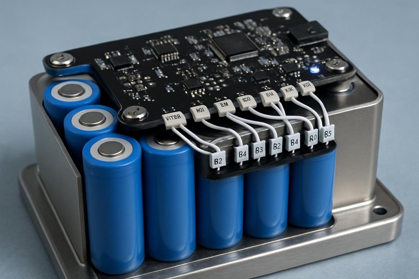
Take a modern EV as an example: a BMS protects the pack by enforcing safe voltage, current, and temperature limits. We monitor individual cells, estimate SoC and SoH, balance where needed, and manage thermal paths to prevent faults from escalating. We combine centralized or distributed architectures with secure communications to keep the system reliable under varying conditions. There’s more to optimize and trade‑offs to weigh, so we’ll guide you through the key choices.
Key Takeaways
- A Battery Management System (BMS) protects a battery pack from overcharge, overdischarge, short circuits, and thermal faults while monitoring health.
- It enforces per-cell voltage limits and safe states to preserve capacity and prevent damage.
- BMS architectures can be centralized or distributed, trading off harness length, fault isolation, and fault-tolerance.
- It uses sensing, synchronization, and communication (e.g., CAN, LVDS) to coordinate measurements and protections.
- It often includes diagnostics, state-of-charge (SoC) and state-of-health (SoH) estimation, balancing, and thermal management integration.
What a BMS Does: Safety, Longevity, and Performance
A BMS protects a battery pack by actively managing safety, longevity, and performance. We implement overcharge, overdischarge, short-circuit, thermal, and fault protections to maintain cell integrity and prevent hazardous events. Our per-cell voltage limits block charging beyond chemistry-specific thresholds, while under-voltage cutoffs preserve irreversible capacity. Fast-disconnect hardware and FETs restrict fault currents to millisecond response times, ensuring rapid isolation during faults. Thermal sensing triggers derating, cooling activation, or pack disconnect when temperatures exceed safe windows. Fault logic enforces safe states and logs events for diagnostics, warranty, and recalls. Longevity arises from balanced cells, optimized CC-CV charging, and DoD management; partial-charge strategies extend cycle life. Performance relies on dynamic current management, low-loss sensing, and targeted derating to sustain power while protecting cells. unrelated topic, off topic.
How a BMS Monitors Cells and Packs
We monitor cells and packs with a synchronized, multi-layer approach that blends precise sensing, robust isolation, and real-time processing. We collect cell voltages with high-precision ADCs, use per-cell front-end ICs, and apply calibration and temperature compensation to minimize drift. We track current with shunts or Hall sensors, perform coulomb-counting, and recalibrate during rest to bound SOC error. Temperature sensors map gradients for thermal management, limiting rates when needed. Insulation monitoring and pack-voltage checks guard against leaks and over/under-voltage, while isolation integrity and ground-fault detection protect both person and pack. We ensure safe connections with precharge and status sensing.
- cell balancing
- insulation monitoring
- pack voltage validation
- safety-fast-path detection
Balancing and Estimating SoC/SoH: Diagnostics That Drive Decisions

We balance and estimate SoC/SoH with a mix of techniques, from Coulomb counting and OCV mapping to model-based observers and data-driven methods. Capacity fade We’ll discuss how balancing strategy—passive versus active—and trigger schemes affect efficiency, heat, and usable capacity across pack chemistries and temperatures. This sets the stage for how SoC/SoH estimates feed reliability, aging predictions, and decision-making in BMS control.
SoC Estimation Techniques
How do we reliably estimate state of charge (SoC) and state of health (SoH) while balancing cells to keep pack performance optimal? We combine Coulomb counting with calibration checks, OC V mapping, and model-based observers to bound drift and adapt to aging. SoC drift and calibration challenges create poorer accuracy if we rely on a single method, so we fuse techniques and reset periodically to maintain trust.
- Coulomb counting with periodic recalibration and temperature-age adjustments
- OCV-assisted recalibration anchors for Kalman-based observers
- Model-based observers providing real-time uncertainty bounds
- Balanced cell voltages reducing estimation divergence during dynamics
Coulomb counting with periodic recalibration and temperature-age adjustments
SoH Diagnostics Trends
SoH diagnostics trends are converging on hybrid approaches that fuse direct capacity checks, impedance proxies, and data-driven insights to deliver robust, real-time health inference under variable duty cycles and temperatures. We combine capacity fade tracking from controlled tests with rapid SOH proxies from DC pulse and EIS, supported by model-based observers for continuous inference without full cycles. Data-driven and ML methods on onboard telemetry—GBDT, LSTM, and transformers—enhance accuracy, with hybrid fusion delivering robustness to diverse operating regimes. Fleet analytics enable fleet-wide baselining, anomaly detection, and cloud-based retraining to capture new failure modes. Digital twins calibrated to fleet data accelerate scenario testing. We monitor SOH diagnostics and correlate them with safety signals to guide maintenance and operational decisions. Fleet analytics remain central to scalable, proactive management.
Balancing Strategy Impacts
Balancing strategy directly shapes SOC estimation accuracy and SOH diagnostics, because how we equalize cell voltages determines the observability of per-cell states and the robustness of state observers. We compare cell-level balancing to pack-level approaches to minimize SOC spread, reduce estimation variance, and sharpen EKF/UKF convergence. The tradeoffs: higher accuracy and dynamic energy recovery with cell-level active balancing versus lower cost with pack-level methods that can misreport SOC after cycles.
- cell level balancing improves per-cell SOC observability and tightens estimation bounds
- SOC estimation tradeoffs center on accuracy vs. hardware complexity and cost
- transient balancing effects must be modeled to avoid SOC recalibration drift
- per-cell telemetry enables precise SOH diagnostics beyond lumped models
Thermal and Power Management in BMS: Limits, Cooling, and Safety
What are the core limits and mechanisms we rely on to keep a battery pack safe and reliable under real-world operating conditions? We rely on thermal boundaries, SOC/SOH feedback, and controlled power paths to manage heat generation and dissipation. Elevated temperatures accelerate calendar and cycling degradation, so we constrain ΔT and maintain safe ranges (roughly 15–35 °C nominal). Low temperatures raise resistance and can cause lithium plating, prompting charging derates below 0–5 °C. Thermal nonuniformity (ΔT across pack) degrades aging and SOC balance, so we target ΔT < 3–5 °C. Cooling options—air, liquid, PCM buffering, and hybrids—balance cost, complexity, and uniformity; PCM provides passive buffering of transient pulses but must be paired with heat sinks. Peak power events require headroom; SOC/temperature estimates set real-time limits to prevent unsafe conditions.
BMS Architectures and Communications: Centralized vs. Distributed
We compare centralized and distributed BMS architectures to highlight wiring and scalability tradeoffs, fault tolerance, and security implications. Centralized designs reduce component count but increase wiring length and single-point failure risk, while distributed systems improve modularity and resilience at the cost of inter-module communication. We examine how these choices affect fault detection granularity, maintenance, and protection schemes as pack size and complexity grow.
Centralized Versus Distributed
Centralized and distributed BMS architectures each offer distinct trade-offs for voltage, temperature, and protection management. We, therefore, weigh centralized control’s simplicity against distributed locality, noting how calibration drift and signal integrity shape reliability. Centralized systems excel with high-precision measurements, but long harnesses can introduce noise; distributed nodes reduce this risk via local sensing and concurrent balancing, enhancing module resilience. In practice, centralized architectures suit small packs, while distributed or modular variants better serve large EVs and energy storage where fault isolation matters. Effective communication topology choices—CAN, LVDS, isolation, and redundancy—determine reaction times and safety margins. Careful clock synchronization and timestamping align pack-level state estimation with local measurements, ensuring coherent control and protection.
- cell stringency
- module resilience
- signal calibration
- fault isolation
Wiring and Scalability Tradeoffs
Wiring and scalability concerns drive the practical tradeoffs between centralized and distributed BMS architectures. We evaluate harness density and connector weight as primary levers shaping performance, manufacturability, and serviceability. Centralized topologies concentrate sensing and control, increasing harness length and connector count, elevating assembly time and EMI risk from dense bundles. Distributed architectures place electronics near cells, cutting high-voltage runs and total conductor length by often over 50%, reducing harness density and potentially lowering overall connector weight. However, more module-level electronics raise per-module BOM and packaging demands, influencing cooling paths and center-of-gravity considerations. Cable routing and shielding choices remain critical to limit EMI and maintain millivolt-level accuracy. Tradeoffs hinge on wiring complexity, harness fatigue under vibration, and the balance between fewer high-current conductors and localized electronics.
Fault Tolerance And Security
What are the core fault-tolerance and security implications when choosing between centralized and distributed BMS architectures? We frame this around risk, diagnostics, and protection effectiveness. Centralized designs concentrate sensing, logic, and protection; a controller or power-supply fault can disable all pack protection, heightening fault tolerance concerns. Distributed architectures localize sensing and control, so a single module failure typically isolates a subset of cells, enabling degraded-but-safe operation and easier containment of security faults. Redundancy lowers single-point failure exposure but adds cost, weight, and complexity. MTBF targets push architectural choices toward limiting single-point risks to meet ISO 26262 safety goals.
- fault tolerance trade-offs between centralization and decentralization
- local detection and isolation advantages in modular designs
- impact of redundancy on security and maintenance
- governance of FW, comms integrity, and OTA updates
How to Choose a BMS: Criteria, Features, and Trade-offs for Your Application
Choosing the right BMS hinges on matching the pack specs, protection requirements, and expected operating conditions to the device’s capabilities, then evaluating trade-offs among cost, complexity, and performance. We assess compatibility with battery chemistry and pack topology, ensuring voltage range, per-cell monitoring, and current margins exceed demands with a 25–50% safety cushion. Protection features—over/under voltage, over-current, short-circuit, thermal management, and redundant monitoring—shape architecture and response timing. We weigh passive versus active balancing, fault-logging, watchdogs, and hard isolation for reliability. In monitoring and state estimation, we favor precise SoC/SoH methods, high-resolution sampling, and temperature-aware algorithms to extend life. For communications, scalability and interoperability drive protocol support, real-time telemetry, firmware integrity, and secure updates within a stream topology-aware, multi-module system.
Frequently Asked Questions
How Does BMS Fault Isolation Handle Failed Cells?
We handle fault isolation by detecting failed cells through per-cell monitoring and impedance checks, then isolating them with bypass or active switches, safely de-rating operating windows, and reconfiguring modules to prevent cascading faults and protect overall pack integrity.
What Are Ess/Industrial BMS Differences From Automotive Ones?
“Lead by example.” We, ESS/industrial BMS teams, differ from automotive ones in Battery thermal management and cell balancing emphasis, prioritizing long-term reliability, modular redundancy, and grid compliance over rapid fault isolation and compact, high-power packaging.
How Is Cybersecurity Integrated Into BMS Firmware?
We integrate cybersecurity through governance and rigorous firmware verification, applying cybersecurity governance across the project and enforcing firmware verification at every update, ensuring secure boot, signed updates, and continuous integrity checks throughout the BMS firmware lifecycle.
Can BMS Support Second-Life or Repurposed Packs?
“Where there’s a will, there’s a way.” We can support second-life considerations with repurposed pack validation, using flexible chemistries, SoC/SoH estimates, and robust safety, monitoring, and modular BMS design for mixed packs.
What Maintenance Data Does a BMS Export to Fleets?
We export Maintenance analytics and Fleet level reporting, detailing Battery health trends and Charging efficiency, to fleets. We present module-level SoC/SoH, cycle counts, coolant temps, DoD, and fault logs for proactive maintenance and optimized operations.
Conclusion
We’ve shown that a BMS safeguards, optimizes, and extends battery life by enforcing safe limits, monitoring cells, balancing, and managing thermal and power needs. It enables reliable operation across fault scenarios and varying conditions, whether centralized or distributed. By selecting architectures and features aligned with your application, you gain transparency and control over performance and longevity. In short, a proper BMS is the backbone of safe, efficient energy storage—keeping you on the right track, rain or shine.

")