You might think this is just swapping batteries, but a marine lithium install demands precise specs, safety margins, and a clear plan from the start. We’ll define performance goals, choose chemistry and capacity, and map out placement, wiring, and BMS integration with fault isolation in mind. We’ll cover charging limits, maintenance, and emergency procedures, then verify everything with thorough tests. Stay with us as we outline steps that prevent failures and protect your crew and gear.
Key Takeaways
- Assess and specify performance goals, SOC ranges, charging limits, and temperature operating limits to guide battery selection and BMS integration.
- Plan placement on a stable, level surface with vibration damping, centered weight, and clear access to inspection points and vents.
- Create diagrams for wiring, include properly rated fuses, traceable labeling, and robust BMS sense line and grounding connections.
- Establish documentation and SOPs for charging, discharging, emergency shutdowns, maintenance, and drills at sea.
- Schedule testing phases for load handling, disconnects, grounding, polarity checks, and controlled charge/discharge cycles with recorded results.
Define Performance Goals and Specs for Your Marine Lithium System
To set effective performance goals, we start by defining the load profile our marine lithium system must support: daily energy use, peak draw, and acceptable reserve margins. We outline clear targets for continuous energy needs, then quantify peak current during startup and high-demand moments. We specify acceptable SOC (state of charge) ranges, charging rates, and temperature operating limits to ensure reliability. We translate these metrics into concrete specs for battery modules, BMS interfaces, and wiring, emphasizing safety-critical clearances and fault isolation. We evaluate design choices with a focus on maintainability and rugged marine conditions. We also weigh cost considerations against longevity and serviceability, selecting components that satisfy performance without compromising safety. This disciplined framing guides subsequent sizing, installation, and integration decisions.
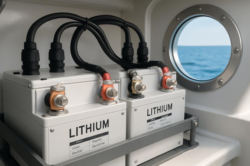
Decide Chemistry, Capacity, and System Size for Your Boat
We’ve defined performance targets for our marine lithium setup, and now we pick the chemistry, capacity, and overall system size that will meet those targets. We’ll evaluate chemistry decisions by prioritizing stability, safety, and charging efficiency, selecting a chemistry with robust thermal management and well-documented fault protection. Next, we assess capacity planning to match expected loads, runtime, and reserve margins, avoiding under- or over-sizing. We’ll calculate usable capacity after depth-of-discharge limits and aging, continuing with a conservative safety cushion for peak loads. We’ll define pack voltage, cell format, and BMS requirements that align with our helm and charger capabilities. Finally, we document assumptions and guardrails, ensuring the chosen system remains scalable, maintainable, and compliant with maritime safety norms.
Plan Placement: Where to Mount and How to Minimize Vibration
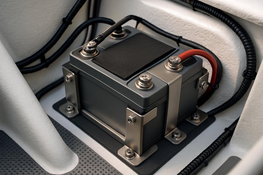
Placement matters as much as the cells themselves, so we’ll choose mounting locations that minimize vibration transfer, maintain accessibility, and preserve safety clearances. Our placement strategy begins with locating batteries on a stable, level surface away from heat sources, exhaust vents, and water ingress zones. We’ll secure enclosures with vibration-damping mounts and strap guides that prevent movement during underway seas. Orientation matters: keep weight distributed evenly, close to the boat’s centerline, and away from high-traffic areas. We’ll preserve serviceability by leaving clear access to inspection points, terminals, and cooling vents. Regular checks for looseness and corrosion become part of our routine. In short, thoughtful placement minimizes vibration, supports cooling, and sustains long-term reliability.
Wire the System: Diagrams, Fusing, and BMS Integration
We’ll start with clear diagram layouts that show component placement and cable routing, ensuring every connection is traceable and labeled for quick checks. Next, we’ll cover fusing fundamentals to protect each circuit branch and establish proper sizing, placement, and accessibility. Finally, we’ll discuss BMS integration to monitor cell balance, temperature, and safety interlocks, so the system operates reliably at sea.
Diagram Layouts
How should the system be wired for reliability and safety? We approach diagram layouts with clear, scalable plans that map components to a logical network. We place the battery bank, BMS interface, and power loads on a single, protected backbone to minimize crossing conductors and reduce fault paths. Each connection uses labeled wires, correct gauge, and dedicated runs to prevent thermal buildup. We document diode orientation where diodes enable OR-ing or isolation, ensuring forward bias conditions are obvious in the diagram. Mast routing is annotated to show routes along the mast and protected channels, with strain relief and water-tight enclosures near termination points. We ensure clear grounding, color coding, and accessible junctions for maintenance.
Fusing Fundamentals
What’s the clearest way to fuse safety with reliability? We begin with fusing fundamentals, installing properly rated fuses on positive supply runs and battery outputs. Choose fuse types and ratings per current draw, cable gauge, and environmental conditions, then verify that fuses interrupt in the expected time for fault scenarios. We place protection close to the source, but away from heat and moisture, with clear labeling and accessible access. Electrical isolation matters: use dedicated, insulated conduit or insulators to prevent accidental contact and cross‑circuit paths. Ring terminals, proper torque, and secure mounting reduce resistance heating. Keep all DC negative rails isolated where practical from hull grounding, and inspect connections for corrosion or looseness before deployment. Documentation, color coding, and routine checks sustain reliability over time.
BMS Integration
To wire the system effectively, we’ll start with clear diagrams that map battery cells, BMS connections, fusing points, and main DC links, ensuring every path is protected and traceable. We’ll design a wired schematic that shows cell groups, parallel/series ties, and BMS input/output signals, then verify routing with a numbered legend. Next, we’ll select fusing strategy aligned to pack current and BMS rating, placing disconnects at accessible points. For integration, we’ll connect BMS sense lines, temperature sensors, and CAN or SMBus communication to our control hub, ensuring robust grounding and shielding. We’ll perform battery safety checks and implement system diagnostics, logging faults for rapid troubleshooting.
| Column A | Column B |
|---|---|
| Diagram clarity | Safe routing |
| Diagnostic readiness | Accessible fuses |
Charge Limits, Maintenance, and Safety Practices
Are charge limits, maintenance routines, and safety practices clearly understood and consistently followed to protect your marine lithium battery system? We explore disciplined management to prevent failures at sea, emphasizing charging limits and humidity control as core safeguards.
Are charge limits and humidity control essential for safe, reliable marine lithium battery operation?
1) Establish charging limits based on manufacturer guidance, monitor temperatures, and log deviations.
2) Schedule regular maintenance checks for connectors, venting, and insulation, addressing corrosion immediately.
3) Maintain a clean, dry storage area with controlled humidity to reduce electrolyte exposure risk.
4) Implement standard operating procedures for charging, discharging, and emergency shutdowns, rehearings on drills.
Together, these practices support safer operations, extend life, and minimize hazards while aboard.
Installation Checklist and Post-Installation Testing
We start with a systematic checklist that covers Pre-Installation Checks, Wiring and Bonding Protocols, and Post-Installation Verification. We’ll verify battery fit, securing hardware, proper grounding, and clear labeling before power-on, then perform functional tests to confirm charging, discharging, and safety interlocks are working. This discussion sets the baseline for safe, reliable operation and identifies any issues early, so you can address them before full deployment.
Pre-Installation Checks
Before we begin the installation, we’ll run a thorough pre-installation checklist to ensure safety and reliability. We’ll verify battery model compatibility, storage conditions, and container integrity before any work starts. This disciplined review minimizes risk and sets a clear baseline for post-install checks.
- Confirm vessel electrical system compatibility and rated outputs.
- Inspect battery enclosure, thermal management, and ventilation for unobstructed airflow.
- Ensure documentation covers installation instructions, safety data, and emergency procedures.
- Schedule testing phases that address load handling, disconnects, and grounding, while keeping discussion ideas and unrelated topics distinct.
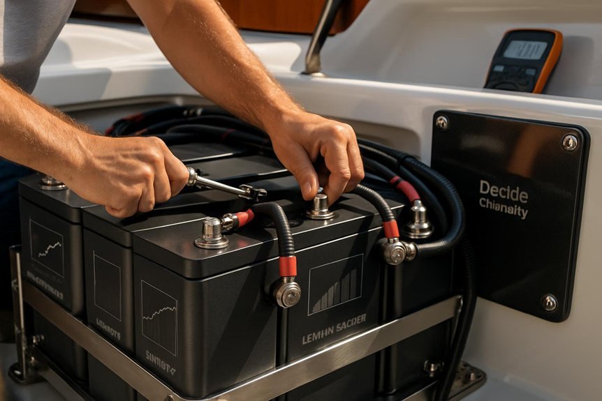
Wiring and Bonding Protocols
Wiring and Bonding Protocols require precise organization and verification from the outset, so we’ll align with the pre-installation checks and proceed with clear, safe steps. We approach wiring best practices with deliberate routing, separation from fuel lines, and secure fastenings to prevent movement. We’ll label conductors, avoid crossovers, and use color-coded insulation to minimize misconnection risk. Terminology and diagrams accompany every step, ensuring traceability and accountability. For bonding safety, we create a single, continuous ground path, verify proper vessel bonding to the hull, and inspect for corrosion or paint insulation that could disrupt continuity. We perform torque checks on lugs and connectors, confirm enclosure seals, and test insulation resistance before activation. Documentation is updated, and a final walkthrough confirms accessibility, checks, and safe operation.
Post-Installation Verification
What’s the most reliable way to confirm a successful installation? We approach post-install checks with a calm, systematic mindset, validating every step from secure mounting to electrical integrity. We’ll follow a concise installation checklist and perform targeted tests, documenting results for safety and compliance. We consider influences like questionable weather and port regulations to ensure our plan remains practical in all conditions. Our testing sequence prioritizes battery health, connections, and protection systems.
- Verify mounting and enclosure seals are intact and vibration-free.
- Confirm polarity, insulation resistance, and continuity on all conductors.
- Run a controlled discharge/charge cycle while monitoring BMS alerts.
- Inspect cooling, venting, and safety devices, recording any deviations for corrective action.
Frequently Asked Questions
How Do I Assess Long-Term Battery Performance Under Saltwater Exposure?
We assess long-term performance under saltwater exposure by conducting controlled saltwater stress testing and tracking corrosion indicators, documenting battery behavior, voltage drift, and capacity loss, then calculating degradation rates to guide preventive measures and safety-conscious maintenance.
What Are Hidden Costs for Professional Marine Lithium Installation?
We’re navigating a ship’s maze, revealing hidden costs for professional installation like hidden reefs; we chart every expense, from permits to wiring safety, ensuring precise, methodical steps and safety-conscious choices before we proceed with you aboard.
Can I Mix Different Lithium Chemistries on the Same Boat System?
Yes, we don’t recommend mixing different lithium chemistries on the same boat system due to safety and performance risks. We prioritize mix compatibility and chemistry compatibility, verifying each unit’s specs and balancing, fusing, and BMS interoperability before any installation.
How Often Should BMS Firmware Be Updated at Sea?
We should update BMS firmware about monthly at sea, adjusting cadence after partial voyages and tests. Our update cadence balances risk, while rigorous firmware testing ensures reliability and safety before each voyage. We’ll document every update for traceability.
What’s the Best Way to Recycle Old Marine Batteries?
We recycle old marine batteries by choosing certified recycling pathways, minimizing environmental impact; we partner with licensed recyclers, demanufacturers, and scrap yards. We guide you methodically, safety-conscious, and we document every step for accountability and traceability.
Conclusion
We’ve covered the essentials to install a marine lithium system safely and reliably, from defining goals to post-install checks. By selecting the right chemistry, sizing, placement, wiring, and BMS integration, you minimize heat, vibration, and fault risk while easing maintenance. A striking stat: properly installed marine lithium packs can reduce charging time by up to 25% and improve cycle life when temps and SOC are managed. Stay methodical, document procedures, and verify every connection before first use.

