We’re not saying it’s flawless, but we can improve it with care. Balancing lithium cells requires clear goals, careful selection of passive or active schemes, and disciplined pre-checks plus ongoing monitoring. We’ll outline safe practices, verify chemistry limits, and align cell voltages while watching temperatures and currents. We’ll integrate with the BMS, inspect harnesses, and tighten connections before any replacement. If you want reliable performance, we should proceed with a structured approach that keeps you prepared for the next step.
Key Takeaways
- Choose passive balancing for small to mid packs; active balancing for large packs or frequent partial cycling to improve uniformity and efficiency.
- Target keep cell voltage spread within 10–20 mV resting, 50–100 mV during cycling, and 20–30 mV for long-term storage with periodic recalibration.
- Use bleed resistors for each cell at top-of-charge, with careful heat and aging management; consider alternative active methods for larger packs.
- Prepare with thorough pre-checks: inspect cells, verify voltages 10–30 °C ambient, and document baselines to ±0.01 V.
- Diagnose issues via per-cell voltages, DCIR, BMS logs, and harness integrity; apply slow recovery charging and reseat connections before aggressive balancing.
Define Balancing Goals for Your Pack (Target Voltage Spread, SOC Alignment, Safety)
How should we define balancing goals for a lithium-pack system? We set precise targets for voltage spread, SOC alignment, and safety to maximize usable capacity while containing aging risk. Resting cell-to-cell voltage spread should typically stay within 10–20 mV for high-performance packs, acknowledging measurement error ±5–10 mV and requiring calibration. Cycling practices may allow 50–100 mV before intervention, but long-term storage aims for 20–30 mV to curb cell aging. SOC variance across series cells should stay ≤1–2% during operation, with periodic voltage-based recalibration to counter Coulomb counting drift and OCV ambiguity. Safety cutoffs must exceed balancing thresholds yet remain below absolute limits, e.g., balance at 4.10 V and charge cutoff at 4.20 V, respecting thermal coupling and aging effects. Factoring in interconnection resistance and temperature effects ensures that balancing targets reflect real-world pack behavior.
Choose Passive or Active Balancing for Your Pack
We compare passive and active balancing by weighing hardware costs, complexity, and long-term efficiency to match pack goals. Passive balancing offers simpler, lower-cost hardware suitable for smaller or hobby packs, while active balancing incurs higher BOM and control complexity but can recover energy in larger systems. We’ll outline how topology, duty cycles, and usage patterns influence decision-making, guiding you toward the most cost-effective balance strategy. Main factual point: Balanced cells support safe operation
We compare passive and active balancing by weighing hardware costs, complexity, and long-term efficiency to match pack goals. Passive balancing offers simpler, lower-cost hardware suitable for smaller or hobby packs, while active balancing incurs higher BOM and control complexity but can recover energy in larger systems. We’ll outline how topology, duty cycles, and usage patterns influence decision-making, guiding you toward the most cost-effective balance strategy. [Balanced cells support safe operation
Passive Balancing Overview
Is passive balancing the right choice for your pack, and if so, what should you expect from its operation? We describe a simple, reliable approach: bleed resistors across cells, activated during the CV phase as needed to converge voltages. Balancing efficiency is limited because energy is dissipated as heat, not transferred; heat management becomes a design focus, especially in larger packs. Thresholds follow chemistry (e.g., 4.2 V Li-ion, ~3.6–3.65 V LiFePO4), with currents typically 10–200 mA per cell. Control is straightforward: monitor voltages and enable resistors on high cells until balance is achieved. The method scales with pack size, but heat and balancing time rise accordingly, constraining large systems.
| Column A | Column B |
|---|---|
| Bleed mechanism | Heat dissipation only |
| Target phase | Top-of-charge |
| Balance current | 10–200 mA per cell |
| Key limits | Heat, duration, aging impact |
| Suitability | Small to medium packs |
Active Balancing Considerations
Active balancing is often the better choice when packs are large or prone to imbalance due to frequent partial cycling. We select active strategies when packs exceed ~10s cells, or kWh-scale packs where wasted balancing energy matters. With frequent partial charges, imbalances accumulate rapidly, and active methods recover energy rather than dissipate it. Switched-capacitor, inductor-based, centralized bus converters, multi-module, and bidirectional isolated converters offer trade-offs in efficiency, speed, and protection. Usable capacity gains of 1–5% are common, with faster charge equalization and potential cycle-life benefits from reduced overcharge/discharge stress. Design must address active isolation and thermal management, ensuring EMI mitigation, control fidelity, and fault handling. Costs rise with pack size, yet heat generation and enclosure cooling improve, enabling safer, scalable implementations. In many systems, active balancing can also provide improved thermal uniformity across cells, which further supports longevity and reliability in high-demand packs.
Prepare Cells and Hardware: Pre-Checks, Tools, and Safety
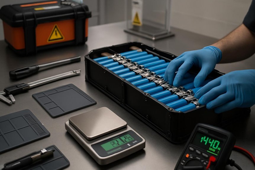
Preparing cells and hardware starts with a meticulous pre-check and a clear tool list to minimize risk and guarantee accurate balancing. We assemble a verified set: metering tools, IR meters, insulated hand tools, wire strippers, and crimpers rated for pack current; a balance charger or adjustable bench supply; and a fireproof work surface with a Li-ion safety bag and a Class ABC/BC extinguisher nearby. We perform visual inspections for damage, confirm each cell’s voltage within 2.5–3.65 V (LiFePO4) or chemistry-specific limits, and verify ambient temperature 10–30 °C. Datasheets guide nominals and currents. We label measurements, document baselines to ±0.01 V, and isolate parallel strings when needed. We ensure grounding, avoid irrelevant topic or extraneous detail, and follow strict insulation and polarity checks.
Do Pre-Balancing and Initial Cell Matching (Top vs Bottom Balance)
What balance strategy should we choose first when pre-balancing and matching cells? We decide based on expected use: top balance for max charge capacity and charging safety, bottom balance for extended usable discharge and easier SoC matching. For new cells, bottom balance suits deep-cycling apps; top balance is common when cells ship partially charged to maximize immediate capacity. For aged or mismatched cells, perform pre-balancing after voltage characterization, replacing outliers rather than forcing balance. Storage plans also drive choice: bottom balance for low-SOC storage, top balance for full-charge storage. Application dictates, with EVs favoring top balance and active balancing, while storage leans bottom balance. Safety, regulation, and failure-mode analysis guide final selection.
| Scenario | Top balance | Bottom balance |
|---|---|---|
| New cells, deep cycle | ✓ | |
| New cells, full-charge use | ✓ | |
| Aged/mismatched | ✓ | ✓ |
| Storage plan | ✓ | ✓ |
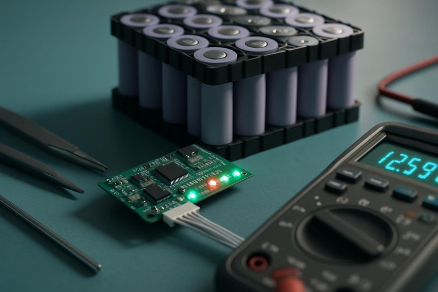
Set Up Ongoing Monitoring and BMS Integration
How should we approach ongoing monitoring and BMS integration to assure reliability and performance over the pack life?
We implement a robust monitoring architecture and ensure data integration flows are secure, timely, and interpretable. We align BMS architecture with pack scale, verify chemistry-specific parameters, and confirm balancing compatibility to prevent drift. Redundancy, fault detection, and clear fault paths keep operations safe during updates or anomalies. We structure sampling for protection loops and for operators’ dashboards, and we define alert thresholds with decisive automated actions. Data retention is staged to support trend analysis without overwhelming storage, while cross-checks guard against sensor drift.
We implement robust monitoring, secure data flows, and fault-aware BMS integration across pack life.
- Define monitoring parameters and sampling cadence for protection loops and ops dashboards
- Validate fault-handling topology, interlocks, and secure communications
- Establish data integration protocols and SOC/SOH exchange with EMS/inverter
- Architect graceful failure modes and cyber/physical security measures
Troubleshoot Balancing Issues and Safety Pitfalls
Balancing issues arise from a mix of cell phenotypes, interconnect resistance, and balancer faults, so we methodically diagnose from per-cell voltages to BMS logs. We begin by identifying spreads >0.05–0.10 V at rest, then perform DCIR tests; >20% degradation flags weak cells. Inspect balance harnesses for >100 mV open-circuit drops under light load, and review BMS logs for repeated cell-high/low events or temperature cutouts. Run a slow balance-charge to observe non-moving cells, which indicate passive-balancer failure or cell defects. Corrective actions avoid immediate replacements: apply a slow recovery charge 0.05–0.1 C, then standard CC/CV, or external balancing with dedicated chargers. Rework harnesses, reseat connectors, or recalibrate BMS offsets, acknowledging wheelhouse risk and balanced safety throughout.
Frequently Asked Questions
How to Determine Acceptable Voltage Spread for Safety Margin?
We determine acceptable voltage spread by defining a safety margin, considering voltage drift, pack aging, and the chemistry’s limits; we target acceptable tolerance per cell, adjust for temperature, load, and measurement uncertainty to establish a robust safety margin.
When to Switch From Passive to Active Balancing?
We switch from passive to active balancing when switching thresholds indicate insufficient correction, especially as charging strategies create rapid imbalances; we adopt active balancing at higher capacity, higher C-rates, or long idle periods to maintain safety and efficiency.
What Are Red Flags During Initial Cell Matching?
We see red flags during initial cell matching: unrelated topic safety myths aside, we’ll measure each cell’s voltage, capacity, and IR, document drift, and reject outliers to ensure uniform packs and reliable performance.
How Often Should Balancing Calibration Be Revalidated?
We revalidate balancing calibration every 3–12 months, depending on pack type and usage, maintaining a safety margin. We monitor delta-V, SOC drift, and cycles, then recalibrate before any risk of imbalance escalates.
Can External Chargers Influence Balance Effectiveness?
External chargers can influence balance effectiveness by managing balance currents and CV hold times, reducing voltage drift across cells. We’ll monitor CAN/SMBus coordination, ensure isolated taps, and adjust profiles to minimize voltage drift during charge.
Conclusion
We’ve walked through a careful balancing workflow, aligning voltages, temps, and SOCs while respecting chemistry limits and ambient constraints. By selecting passive or active balancing appropriately, performing methodical pre-checks, and maintaining vigilant monitoring through the BMS, you reduce stress and aging across cells. Think of the pack as a synchronized orchestra, where every cell must hit its note on time. Stay disciplined, document calibrations, and review logs regularly for reliable performance and safety.
")
