Charging curves sit at a crossroads: they reveal how a battery accepts energy under BMS, yet they often obscure the exact constraints we must plan around. We’ll examine how SOC, voltage, and temperature shape the fast-charging window, taper onset, and long-term health, then translate those insights into practical charging strategies. Stay with us as we connect theory to station timing, cost efficiency, and longevity without assuming a one-size-fits-all curve.
Key Takeaways
- A charging curve plots how a battery accepts energy over SOC or time, reflecting BMS control, chemistry limits, and temperature.
- Key features: soft start, a high-power window (roughly 10–60% SOC), and a taper as voltage rises toward full charge.
- SOC and per-cell voltage drive current: low SOC allows higher current; taper begins near CV as cells reach voltage limits.
- Temperature, age, and chemistry shift curve shape, affecting peak power, onset of taper, and overall charging time.
- Chargers negotiate power via DC or AC paths and safety interlocks, with practical peak defined by the weaker of charger capability and vehicle acceptance.
What Is an EV Charging Curve and Why It Matters
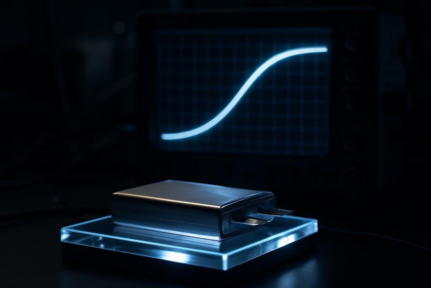
What is an EV charging curve, and why should you care? We define it as a plot of charging power or current versus SOC or time, revealing how a battery accepts energy. The typical shape starts slow at very low SOC, ramps rapidly to a mid‑SOC plateau, then tapers markedly above about 70–85% SOC. This curve reflects BMS control logic, cell chemistry limits, thermal constraints, and charger capability. Understanding curve semantics helps you plan charging sessions, target the high‑power window (e.g., 10–60% or 20–80%), and optimize dwell time for cost and convenience. It also informs station utilization and route planning, since energy per minute varies across the curve. Avoiding frequent full‑SOC fast charging reduces wear, balancing calendar and cycle degradation against practical charging needs, and highlights taper implications for strategy. Temperature and battery technology nuances influence the curve, meaning that same charging numbers can feel different across weather and chemistries and system voltage architecture.
How SOC and Voltage Drive Your Charging Behavior

We’ll show how SOC governs where power is delivered and how voltage limits shape that delivery, from initial CC to the taper in CV. As SOC changes, current shifts—high at low SOC, sustaining through 20–80%, then tapering near 100% to protect cells. We’ll also connect per-cell voltage limits and pack behavior to explain why the 80% rule and voltage margins matter for charging speed and safety.
New sentence with bracketed main factual point:
Charging curves can vary between chemistries, so even with the same SoC, different packs may draw power differently chemistry-dependent.
Bracketed main factual point:
[chemistry-dependent
SOC-Driven Power Shifts
Why does charging feel faster at the start and slow down as it nears full? We, the operators of this system, explain how SOC and voltage shape power delivery. SOC zones constrain allowable current: 0–20% lets peak DC fast charge; 20–80% sustains high power; 80–100% tapers current as CC transitions to CV. SOC buffers, often 5–10% at top and bottom, cap usable SOC to protect longevity and margins. Pack limits hinge on the weakest cell’s SOC/temperature, so overall power is governed by the most restricted element. Cell voltage rises nonlinearly with SOC; near-full voltage triggers CV control and current taper, with voltage hysteresis and load offsets requiring compensation. Thermal coupling and safety cutoffs further induce abrupt, SOC-driven power limits. SOC is the core metric that translates energy content into charging behavior, and its accuracy in the BMS underlies safe and predictable charging.
Voltage Marks Charging Pulse
Voltage marks guide how we pulse-charge, pairing SOC estimates with cell voltage signals to shape power delivery. Our methods hinge on voltage thresholds, hysteresis, and relaxation behavior to tighten SOC accuracy while safeguarding cells. We fuse voltage markers with adaptive timing to balance efficiency and safety.
- Voltage relaxation informs true SOC during post-pulse dwell, reducing misestimation from transient overshoot.
- Temperature compensation shifts voltage-SOC curves, requiring on-the-fly adjustments to maintain alignment across environments.
- Per-cell voltage control enables targeted balancing, where peak tracking triggers bleed or bypass to prevent local overcharge.
We synchronize pulses with instantaneous voltage responses and thermal signals, using adaptive PWM to respect electrochemical limits. This approach yields precise, conservative top-offs, leveraging voltage marks to refine both charging cadence and safety margins.
From Soft Start to Peak: Capturing the Fast-Charging Window
We start with a compact view of how soft-start sets the stage for a true peak, where current and thermal limits interact over the 0–40% SoC window. We’ll compare peak-power dynamics across chemistries and architectures, highlighting how 800 V systems sustain higher kW with lower current and how BMS pacing shapes the plateau. Finally, we outline how tapering and hardening rates compress the fast window, emphasizing SOC-taper effects and the practical implications for charging throughput.
Peak Power Window
So, how exactly does the fast-charging window emerge from soft start to peak, and what defines its boundaries? We define it where voltage and impedance align to permit peak current without triggering limits, with soft start shaping the ramp and thermal constraints capping duration.
- The BMS and CCS/CHAdeMO negotiations set peak onset, balancing cell voltages, temperatures, and diagnostics against safety margins.
- Cell chemistry and design dictate acceptance rates, with high-nickel chemistries often delivering higher peak power than LFP at mid-SoC, while thermal management lengthens the window.
- Hardware and topology—HV architecture, cable ratings, and charger output curves—determine practical peak duration within the theoretical window.
Environmental shifts, ambient temperature, and grid constraints further tighten or extend this window, reflecting battery logistics and thermal constraints.
SOC Taper Dynamics
How does the fast-charging window emerge as we move from soft start to peak, and what marks its boundaries? We describe SOC taper dynamics with a precise sequence: soft-start, bulk CC, CV taper, then final top-off, where the current recedes as SOC climbs. Subtopic relevance lies in tying electrode kinetics, diffusion limits, and impedance growth to observable curve interpretation, yielding a sharp transition when voltage headroom narrows. The taper steepness rises with SOC because intercalation kinetics slow and charge-transfer resistance increases, forcing current reduction to keep voltages in safe bounds. BMS strategies shift from CC to CV, fine-tuned by temperature and age. Balancing activity intensifies near 100% SOC, reinforcing the need for reduced current. This framing clarifies how the fast-charge window is captured and validated.
Hardening Rate Factors
Could the fast-charging window be narrowed simply by thermal and material constraints as we move from soft start toward peak? We think so, and our view is data-driven. We tighten the window with precise control of thermal management, aging modes, charge protocols, and control algorithms to maximize safe peak current.
- We optimize active cooling to raise allowable charge power by 20–50% in high-power sessions, extending the fast-charge envelope without accelerating SEI growth or electrolyte oxidation.
- We tune soft-start ramps to minimize overpotential, reduce plating risk, and shorten the soft-start duration across temperatures from ~10°C to ~45°C.
- We implement predictive BMS routines that adapt ramp rates and duty cycles based on impedance, temperature, and SOC to stabilize the hardening rate.
These factors collectively shape the hardening rate, balancing speed and longevity.
When Taper Begins and Why It Matters for Stops
What exactly triggers taper in DC fast charging, and why does that timing matter for your stop planning? We synchronize our charging strategy to electrochemical limits, because taper onset occurs as cell voltage rises and internal resistance increases, prompting the BMS to throttle current to protect cells and balance voltages. High-voltage (800V) packs push taper to later SOCs (60–70%), while 400V systems begin earlier (30–50%). The practical effect is that energy delivery slows during the final segment, making the 80%–100% window disproportionately long. For short stops, target 10–80% to maximize energy per minute before taper dominates. Planning should anticipate variability across models, thermal conditions, and station headroom, avoiding extended dwell in the tapered phase and optimizing overall charging efficiency. taper onset guides stopping rules and scheduling.
How Temperature Affects Charging Speed and Safety
Temperature shapes charging speed and safety by modulating ion mobility, reaction kinetics, and thermal management behavior. We, the authors, analyze how temperature shifts affect acceptance power, plating risk, and thermal gradients that drive degradation. Battery longevity hinges on keeping cells near 20–40°C, where kinetics are favorable and internal resistance is minimized. The BMS actively tunes currents to protect cold cells, while thermal modelling informs preconditioning and active heating strategies that unlock higher power quickly.
- Cold packs trigger reduced current to prevent lithium plating, extending life but slowing charge.
- Preconditioning and active heating raise temperature, increasing DC fast-charge acceptance and reducing taper length.
- Thermal management energy use trades range for speed, with heat pumps typically outperforming resistive heaters.
We emphasize careful thermal modelling to balance safety, speed, and battery longevity.
Charger Power, DC vs AC, and What Your Car Negotiates
Charger power isn’t simply what a station advertises; it’s the actual energy delivered to your battery, constrained by vehicle acceptance, cable rating, site power, and state of charge. We analyze how AC and DC differ: AC charging hinges on the onboard AC–DC converter, so the wall supply may be higher than what the car accepts; DC charging bypasses that bottleneck, delivering direct DC to the pack but still limited by vehicle BMS, cooling, and connection. Negotiation protocols (ISO 15118, Plug & Charge) manage max current, voltage, and safety interlocks, while grid constraints and station load management cap per‑vehicle power. In practice, charging etiquette and stall etiquette matter: predictable ramping, minimizing dwell, and courteous pacing improve efficiency and grid flow for all.
Reading Real-World Curves: Key Metrics You’ll Care About
We’ll start by tightening the lens on peak power windows and taper dynamics to translate curve shapes into actionable metrics. By comparing how long a car sustains near-peak kW and where the taper begins, we can estimate energy delivered within the high-power window and the practical time-to-80% charging milestone. These insights bridge manufacturer specs and real-world performance, guiding trip planning with kWh per minute and energy-added metrics.
Peak Power Window
How do you identify the peak power window on real-world charging curves, and why does it matter for throughput planning? We define it as the SOC range where DC power stays within 90–100% of the vehicle’s max, and note that the typical window centers around 10–60% SOC, often 20–50%. This window drives throughput, charger count, and dwell-time estimates, influencing site-level planning and daily kWh-per-charger.
- Peak width, SOC start–end, at 90% threshold, normalizes comparisons across vehicles.
- Peak energy and duration quantify usable fast charge per session.
- Average peak power and utilization gauge real-world efficiency versus capability.
Factors to watch include battery temperature, initial SOC, and site constraints; these drive battery degradation risk, and we should observe charging etiquette to avoid unnecessary bottlenecks.
Taper Dynamics Insight
Understanding taper dynamics starts with real-world curve reading. We examine how taper initiation marks the CV transition, typically around 60–80% SOC, yet varies by chemistry and pack design. The voltage plateau emerges as the cell approaches the charger clamp (roughly 3.9–4.2 V/cell), while current falls along an exponential or negative-log path; we quantify slope with dI/dt to compare packs. Temperature accelerates or delays onset, with higher temps advancing taper and suboptimal ranges suppressing acceptance. Aging and higher impedance pull taper earlier, and degraded SOH sharpens the effect. In practice, we measure energy-per-minute and time-to-half-power to plan sessions, noting that 80–90% often dominates, while 90–100% yields diminishing returns. Taper initiation and voltage plateau define the real-world balance between speed and efficiency.
Modeling Options: Simple Fits vs Electrochemical Models
Differences in complexity and fidelity define the choice between simple fits and electrochemical models for charging curves. We present a concise framework that aligns with practical BMS constraints and physics insight.
- Simple fits offer fast calibration and real-time applicability using ECMs or OCV-SOC relationships, with temperature calibration limited to lookup tables or simple scaling.
- Electrochemical models (DFN and reduced-order variants) provide higher fidelity, capturing gradients, kinetics, and thermal coupling, but demand extensive parameterization and higher compute costs.
- Hybrid approaches blend blocks with learned corrections to balance accuracy and speed, aiding aging extrapolation while controlling inference load.
In practice, temperature calibration and aging extrapolation guide the choice: simple fits excel in stable regimes, while physics-based models better handle aging and diverse temperatures.
Planning Trips With Charging Curves and Timing
Planning trips around charging curves requires a precise blend of vehicle capability, charger specs, and timing. We match vehicle max DC fast-charge with charger output, using the effective peak as the minimum of the two, and account for connector compatibility and adapters that may reduce usable power. We rely on ACP metrics from real sessions to predict delivered power versus nominal peak, and we consider site-level limits and feeder constraints that can throttle multi-vehicle use. SoC windows guide pacing; fast charging hits peak between ~10–20% and ~50–80%, while 80–100% charging is slow. Arrival SoC buffers of 10–20% prevent slow ramps. We evaluate marginal travel time vs charging time, planning for reliability, uptime, and redundancy. Out of scope inference and legal considerations frame our cautious, data-driven approach.
Practical Strategies for Longevity and Cost Efficiency
Are we getting the most value from every kilowatt-hour by balancing SOC, charge rate, and temperature? We answer yes, with a disciplined approach to longevity and cost efficiency. Our strategy hinges on SOC windows, moderated fast charging, and thermal discipline to minimize degradation while trimming expenses.
- Maintain a daily SOC of ~20–80% to reduce high-voltage stress; store at ~40–60% for long gaps, avoiding 0% or 100% unless needed.
- Use DC fast charging sparingly; target 60–80% when necessary, then resume at destination to limit taper heat and cycle stress.
- Prefer Level 2 charging and preconditioning; align with TOU tariffs to unlock lower rates and maximize battery economics.
We follow charging etiquette, with proactive thermal management to curb resistance rise and calendar fade.
Frequently Asked Questions
How Does Battery Chemistry Specifically Alter the Taper Rate?
We’ve observed that battery chemistry sets the taper rate variability: intercalation vs. conversion, solid-solution vs. two-phase, and SEI dynamics shape charging curves; these factors drive real time BMS optimization and our taper rate expectations.
What Role Does Ambient Temperature Play in DC Fast Charging?
Ambient temperature heavily governs DC fast charging, shaping charging speed variability through battery thermal management and charging infrastructure interaction; user behavior impact and DC fast charging etiquette matter as preconditioning and temperature management influence outcomes.
Can a Car’s BMS Optimize Charging Curve in Real Time?
Yes, we can optimize charging curves in real time. We continuously adapt current targets with adaptive cooling, monitor gravity effects as applicable in weighting thermal and impedance feedback, and adjust to maintain safety and efficiency.
How Reliable Are Public Charger Power Ratings Across Stations?
We’d say public charger power ratings are unreliable across stations. Variability from charging standards, site constraints, and communication faults reduces usable power; pricing transparency and standardized reporting are essential for meaningful comparisons.
Do Charging Curves Differ Between EV Makes/Models at the Same SOC?
Yes—EV performance and charging curves differ at the same SOC across makes/models. We see varying peak/sustained power, influenced by chemistry, cooling, and BMS. Understanding charging etiquette helps manage expectations during rapid charging sessions.
Conclusion
We’ve laid out the logic, lit the lens, and linked layers of loading. By parsing parameters—SOC, voltage, temperature, and taper timing—we can predict practical charging windows and optimize occupancy. With precise planning, peak power is preserved, cycles are spared, and costs stay controlled. Read the curves, report the reality, and refine routines. Practical, proven pacing, paired with prudent purpose, propels performance, preserves longevity, and keeps trips timely, tasty, and technically sound.

")